

The importance of automotive steering knuckle forging
2024-01-16
Steering knuckle is one of the main parts on the steering axle of the car, which can make the car drive stably and transfer the driving direction sensitively. One role is to effectively transfer the steering wheel rotation angle value to the front wheels of the car, timely control of the automobile route, so as to ensure the safety of the car; another role is to bear the front of the car load, support and drive the front wheels to rotate around the main pins, in the automobile driving state, bear the impact of variable loads. Therefore, the steering knuckle not only requires reliable strength, but also must ensure its high processing accuracy. Its geometric shape is more complex, more geometric shapes need to be processed, the positional accuracy between the various geometric surfaces requires high precision, and its machining accuracy will affect the steering accuracy of the automobile in operation. In this paper, through the analysis of two different forging process production of forgings, to explore the steering knuckle forging die form, margin allocation and forging error and other impact on its machining process, and in the processing of jig design and positioning surface selection and other aspects of the proposed reference.
Steering knuckle structure characteristics
The shape of the steering knuckle is relatively complex, concentrating the structural characteristics of four types of parts such as shafts, holes, disk rings, fork racks, etc. It is mainly composed of three major parts: the supporting shaft, flange, and fork rack. The structural shape of the supporting shaft for the stepped shaft, its structure is characterized by the coaxial cylindrical surface, tapered surface, threaded surface, as well as perpendicular to the axis of the shoulder, the transition fillet and the end face of the rotating body; flange part of the flange including flange surface, through-hole coupling bolts and steering restriction of the threaded holes; fork is composed of the upper and lower lugs by the steering knuckle and the flange surface of the fork frame-shaped structure.
From the perspective of forging process, the steering knuckle forgings are characterized by: long and thin support shaft, flange is larger and sometimes for the shaped surface, the fork frame and the support shaft centerline deflection of an angle α and complex shape, according to the "GB12362-2003 steel die forging tolerance and machining allowances," forging for the typical complex fork-shaped parts.
Steering knuckle machining process
The main process of steering knuckle machining is as follows: milling journal end face, drilling center holes at both ends → rough turning flange end face and support shaft journal → semi-finish turning, finish turning support journal, rounded corners, finish turning flange, end threads → drilling, tapping flange surface threads → rough and fine milling upper and lower earrings inner and outer end faces → rough drilling, fine boring of the main pin holes → surface quenching (according to the need) → fine grinding of the large and small bearing necks and rounded corners → marking → inspection, Into the warehouse.
Influence of forging method on processing technology
1. Forging method
Steering knuckle forgings production has two forging forming process: horizontal die (plane die) and vertical die (vertical die). Horizontal parting die is the forging center plane for the parting die surface of the forging method, because the support shaft part of the flange and fork frame part of the cross-section of the large difference in the forging process for the reasonable distribution of blanks, resulting in a very complex billet making. Even so, in the support shaft and flange connection there will be a large fringe, and gradually reduced along the axial direction, until the end to reach the normal width, this way of forging material utilization is low. Vertical die splitting based on the center plane of the flange, taking into account both sides of the fork cavity, this forging method can be used in the pre-forging of closed forging technology, positive extrusion of the shaft and reverse extrusion of the two sides of the fork, and then the final forging shape and discharge of excess metal.
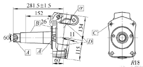
Due to the different production methods of forgings, the arrangement of the parting surfaces, the allocation of machining allowances as well as the misalignment and thickness tolerance of forgings in the design of forgings will have different effects on the processing of the steering knuckle. Especially in the milling journal end face drilling center hole, turning, grinding support journal (see Figure 1 in the A, B parts of the processing) and flange end face, processing flange and steering knuckle arm and brake coupling threaded holes, as well as the processing of fork frame part of the fork end face and the main pin hole and other processes (see Figure 1 in the C, D parts of the processing) to produce a particularly pronounced impact, so in the machining process design, selection of jig positioning surface Must be based on the production of forgings in different ways and take corresponding countermeasures.
Steering knuckle machining parts schematic
2. Forging tolerance and machining allowance arrangement
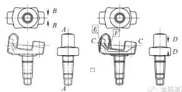
In the use of horizontal split die forging steering knuckle, its split die surface is usually selected in the largest cross-section, as shown in Figure 2 can be seen, A-A for the forging split die surface, and forging direction perpendicular to the plane of the split die surface, that is, along the direction shown in B-B. So that the forging by the upper and lower mold two parts of the forging molding. The machining allowance of the forging part is evenly distributed in the support shaft, flange end face and upper and lower fork end faces. Forging the pulling die slope along the forging direction, that is, the direction of B-B, generally 5 ° ~ 7 °; in the forging process, due to the forging temperature and forging force and other factors such as fluctuations in the impact of the upper and lower mold can not be completely hit by, so in the forging will be formed along the forging direction of the thickness of the size of the fluctuations in the usual tolerance of ± 1mm; and due to the upper and lower mold error generated by the misalignment of the general ± 1.5mm.
Vertical split die forging parting surface selected perpendicular to the support axis and through the center of the flange, but the shape of the forging piece determines the parting surface for a curved surface. As can be seen from Fig. 2, the surface shown in C-C is the parting surface, and the forging direction is perpendicular to the parting surface, i.e. along the direction shown in D-D. The forgings produced in this way are different from the forgings produced by horizontal forging in terms of machining allowance allocation. Due to the need of pulling die of the upper die forgings, no inverted pulling die is formed, so the allowance needs to be added on the inward tilted side of the upper and lower forks to form a positive pulling die, and the main parts are as shown in the E and F parts in Fig. 2. And support shaft part in addition to the normal add margin, in order to facilitate the support shaft part of the mold, along the axial addition of 1 ° ~ 1.5 ° pulling angle, assuming that the support shaft length of 200mm, due to the addition of pulling angle, from the small end of the shaft to the flange root to support the shaft of the outer neck of the extra added margin will be increased from 0 to 0.35 ~ 0.5mm, the extra margin of d = 200tan (1 ° ~ 1.5 °). The thickness tolerance of the forgings is usually ±1.5 mm, produced along the D-D direction, and the misalignment is usually ±1.5 mm, produced perpendicular to the D-D direction.
Schematic diagram of horizontal and vertical split-die forgings
3. Processing factors
The above two ways to produce forgings exist in the margins and tolerances and other factors of different impacts, in the machining process design must be taken into account, otherwise it will have an impact on the processing quality of the steering knuckle. Need to focus on the impact of processing are:
(1) steering knuckle support shaft part of the processing of steering knuckle support shaft part of the processing of the main process for milling the shaft end face, drilling the center hole, as well as turning, grinding parts of the journal (see Figure 1 in the A, B parts). These two processes are interrelated, especially the drilling center hole process, the center hole is not only the subsequent processing of the support journal positioning reference, but also the support shaft on a variety of dimensions, positional tolerances of the measurement reference. In the machining process, if the two center holes of the line can not match the axis of the support shaft forging, will cause uneven distribution of the forgings and the emergence of machining journal oxide skin (i.e., residual forging surface). Comparison of the two ways of production of forgings journal parts can be seen, for vertical split-die forging of the steering knuckle, due to the support shaft part of the final forging is shaped in a cylindrical cavity, so the part of the roundness is good, the allowance is uniform, in the machining of the center hole to choose the positioning position is relatively easy. Horizontal forging forgings due to the error and thickness tolerance, as well as cutting edge residue and other factors, the part will form an irregular round, the journal of the various parts of the multiple factors affecting the distribution of the allowance fluctuated significantly. Based on this shape fluctuations in the journal of the forging parts, in the processing of the center hole positioning position selection should be considered along with the parting surface into 45 ° direction using V-shaped fixture design, so as to avoid the impact of the flying edge residue and error, so that the center hole line tends to be close to the theoretical centerline of the journal of the forging parts, so as to make the subsequent machining of the amount of uniform distribution.
(2) support axial size Figure 1 shows the axial dimensions of the steering knuckle chain 281.5mm, 26mm, 60mm and 11mm relationship is interrelated, the steering knuckle wall thickness of the main pin hole size of 11mm is particularly important, which is related to the strength of the wall thickness of the main pin hole, and therefore must be ensured. From the analysis of the interrelationship of the axial size chain, wall thickness fluctuations in the first machining process milling end face to play the center hole should be considered from the different forging methods to axial positioning problems, if it is a horizontal forging forgings, then the forging of the axial dimensions of the forging part of the upper and lower molds, the main effect of its fluctuations in forging misalignment. And if it is vertical forging production of forgings, axial size part of the forgings produced in the upper and lower two molds, the fluctuation of its axial size is mainly for the forging thickness tolerance, so in this state when selecting the initial axial positioning size is recommended to select the wall thickness of the main pin hole in the same piece of mold produced by the upper mold, i.e., select the flange surface near the fork part.
(3) flange processing vertical forging forgings of the flange part is formed in the complete cavity, so its shape error fluctuations are small, in the processing of the flange around the connection hole, as long as the positioning of the center hole of the support shaft is accurate, the wall thickness around the connection hole will be very uniform. And for the horizontal forging production of forgings, its flange part of the forming is formed in the upper and lower two molds, and due to the forging error and thickness tolerance, and at the same time, according to the above analysis of the centering of the center hole, so in the processing of the flange part of the connection holes around the hole, there is a hole around the wall thickness is not uniform, or even the risk of bias is small, it must be paid attention to, and if necessary, you can ask for the individual holes around the appropriate addition of margin, to avoid this risk. In addition, the vertical forging of the forging flange thickness by the forging thickness tolerance, different batches of forging flange end face of the machining allowance will fluctuate, this point in the processing also need to pay attention to.
(4) steering knuckle fork processing because the steering knuckle support shaft part and its fork part of the existence of an angle α, in the use of vertical forging production steering knuckle, in order not to produce the inverted mold pulling, so that the upper die part of the forging can be released from the cavity, must increase the allowance. In the E and F parts shown in Figure 2, especially the F position of the allowance is large, assuming that α = 7 °, fork depth of 70mm, the normal pullout skew is 3 °, then the fork root to increase the allowance for: δ = 70tan7 ° + 70tan3 ° = 12.2mm. so that in the fork machining, especially rough machining process must be taken into account in this part of the large allowance of the cutting; and horizontal forging forgings In these parts of the allowance can be arranged in accordance with the conventional, so the amount of cutting is smaller, but because of the two fork mouth in the middle of the part of the existence of extracting the die allowance, in order to ensure the accuracy of the center hole, the part will generally be end milling. In addition, in the processing of the fork part, usually with journal positioning, for vertical forging forgings, due to the influence of the error, the fork part of the machining allowance will change, and the seriousness of the machining allowance will be insufficient to produce oxidized skin.
Latest News


Located at No.57, Weiqiao Aluminum Deep Processing Industrial Park, Binzhou City, Shandong Province, China
Copyright © 2023 Shandong Sennai Technology Co., Ltd SEO 国际站建设:中企动力 淄博 外贸Google推广
Welcome your advice message
